The Tycobrahe Parapedal was unique in that it used two pots to create it's own incredible wah type sound. The Parapedal was made in the mid seventies by Tycobrahe Engineering and has become quite a collectors item, that is - if you can find one. They were made in such small quantities that their value has sky-rocketed. Ask any vintage effect dealer for one(if they can find one).
What I do know is that Geezer Butler and Tony Iommi both used one, and that's enough of a reason for me to build one. Just listen to N.I.B. and you'll hear it on Geezer's bass solo intro.
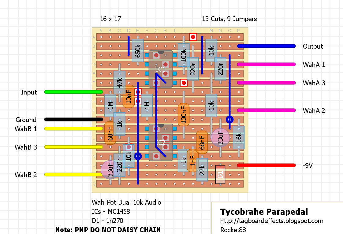
Original was Positive Ground:

Cool!
ReplyDeleteWhere I can get that dual 10k pot for wah?
honestly, you can just use a regular alpha. that's what the chicago iron clone uses, and if you contact them for a pot they'll charge you like $15 for a pot we get at tayda for $0.50. i know there are some other wahs that use dual pots, so joe gagan might have one.
DeleteNice one Zach. Didn't know Geezer and Iommi used these, now I have to build one. NIB rules.
ReplyDeleteGot any suggestions on where to buy the pot?
see if joe gagan has any or these at tayda should work,
Deletehttp://www.taydaelectronics.com/10k-ohm-logarithmic-dual-taper-potentiometer.html
Is that a 4 point jumper between the IC's?
ReplyDeletewhen you look at the schematic pins 3 & 5 of both IC's are connected to each other, and they all connect to the the 9V at the 22k/16k junction. so to make life easier i put individual jumpers between pins 3 & 5, then ran a jumper connecting both pin sets. so really it's 3 jumpers together.
DeleteI'm sorry to be "The Jerk", but at least the positive ground version is surely wrong. Any dual opamp is expecting the -VCC on pin 4 and the +VCC on pin 8. Now in the positive ground version you have it the other way around: -9V (would be -VCC) is applied on pin 8 and GND (would be +VCC) on pin 4.
ReplyDeleteHey man. You're actually not being a jerk at all, but you happen to be wrong in this instance. The schematic, which was made from an original pedal, hs the power that way. Yes, you are right that the IC is expecting opposite voltages, what is normal for NPN devices, but this effect was Made PNP with an NPN IC. It doesn't make sence, nor does the extensive power filtering network, but that's the design. It's based off of R.G. Keen's schematic and PCB layout, which is posted on geofex. It makes no sense, but I've double and triple checked that it's right, and have been following the DIYSB thread on this pedal.
DeleteWell... I've checked the FSB thread for this effect, and if you check the PCB layout on geofex (http://www.geofex.com/FX_images/newparapedal.pdf) you will see that the "Battery (-)" connection goes to pin 4 via the reverse polarity protection diode. I've checked R.G.'s schematic, but that does not state clearly which power connection goes to which pin, however the PCB layout makes it clear and then it also makes sense (even though making this effect positive ground does not make much sense at all in general... But certainly would work)
Deleteah, i see what you mean now. according the the DIYSB thread people were actually just switch the reversing the polarity on the PNP, switching around the diode, and electros and "turned" it into an NPN device. i went back and looked the the PCB from R.G. Keen, and made the correct to the power for the PNP layout, so it should be ok. me personally though plan to build the NPN layout, mostly because of the ability to daisy chain.
DeleteNow it looks better, but I would pull the link that goes to pin 4 all the way down to the last row. That way you will get the filtered and polarity protected -9V (now it only gets the "bare" incoming -9V). And I also agree: the convetnional negative ground version makes much more sense to me too. Btw. I think "PNP" and "NPN" are not the correct terms, but rather "positive ground" and "negative ground". PNP and NPN are transistor technologies and the MC1456 IC as both types in it. Also PNP transistors can be used in negative ground circuits as well - see the EQD Crimson Drive for example. And again sorry to be the "nomenclature nazi"...
Deleteno man, i'm just as much of a stickler for using the right terms, and you're spot on. the only reason i used NPN and PNP to describe both circuits is that to a lot of people on the blog may not understand that, but know the terms NPN and PNP, and as such from other pedals they associate PNP with positive ground, and NPN with negative ground. i want to try and prevent someone from building the positive ground one and end up running it negative ground and come back not understanding what they did wrong.
DeleteOh, and one very important thing: thank you very much to keep this blog alive. One of my all time favourites and a great DIY resource.
ReplyDeleteI've been wanting one of these for a long time. And it so happens I have an empty wah shell lying about waiting for a project. If anyone's looking for another example of Geezer using the Tycobrahe, he used it on Sign of the Southern Cross.
ReplyDeletehttps://www.youtube.com/watch?v=wpVHWWHNpV4
How does one mount a regular pot into a wah though?
hey man. you do it the same way you mount a wah pot. you use 2 washers, one on each side of the mount in the enclosure, and a nut on the outside to hold it in place.
DeleteYou will possibly not be able to fit a regular Tayda Alpha 16mm pot in a wah, as the threaded portion of shaft is not long enough. Better to use a dedicated wah pot, if you can find one at the right value, or alternatively use a 24mm LONG shaft Alpha or CTS pot, like the ones fitted to a Gibson Les Paul.
DeleteI would also use thicker washers than the ones supplied with the pots.
i completely agree beaker. a wah pot or long shaft pot is much better, but you can use a regular alph. i did for the dbd in a wah without any issues. the only issue is the nut can't be tightened too much because there's not much threads on the end when you insert it into the mount.
DeleteThere needs 2 be a jumper on pin 7 top IC. Going to that 10k, next to wah a3. Then it works. Yet only in a certain part of the taper, then it cuts out! That 1m in between the Ic's Im not sure whether its supposed to be there. And then in rg keen schematic theres another 10k in there. Between pin 7 ic2 going to pin6 ic 1. I tried a 100k reverse log and that gave it better sweep. But still isn't right.
ReplyDeletehey man, nice catch about the missing link. not sure how i missed that one. i'll update the layouts.
Deletejust to address a couple of things you mentioned. the 1M resistor in the middle is actually a pull down resistor near the output, which connects to ground at one end, and the junction of C5 and R8 on the schematic, or the junction of the 100nF cap and 220r resistor which goes to output on the other end. so that's not a problem at all, and i'm not sure where you're seeing another 10k, according to the scheamitc there should be 3, and there are.
as to the the cutting out problem. part of the problem with building anything in a wah is that you need to set the pot at the correct place to get the desired sweep. you don't want to go with a different value, you need to adjust the start resistance and end resistance, because you don't get the whole sweep of the pot. in fact i think it's like 60% in a standard crybaby style wah, don't quote me on the exact amount. by going to something with a 10x higher resistance, you're going to blow right past the 10k you need. assuming you get 60% of the pots value in a you're getting a sweep range of 60k, vs 6k that you should be with the 10k pot, so you're only in the range for a short travel distance of the treadle. i suggest disconnecting the pot from the treadle, turning it on and finding the point at the beginning and end where it works then set the gear.
Agreed. I put a Pearl Vorg Warp Filter Fuzz in a Crybaby shell a few weeks ago (photos in the "show your pedal guts" thread), and that took me a good hour to find the best possible sweep from the gear rack on the pot. Other wahs might cover more rotation, but I think Zach is about right with his figure of around 60% sweep with a Crybaby.
Deleteyea man, some do cover more, like the colorsound wahs. i have to go back and check my notes on some wahs i've done, cause joe gagan told me the amount of travel you get. don't remember the exact number, but 60% is stuck in my head for some reason.
Deletebtw, i had the same issue with the dbd in a wah shell. to get it right i did have to use a larger value pot so i had the right rotation, then setting it up to the right spot was an hour or so. what a bitch, but so much fun in the end and totally worth it.
Hey Hey. I was looking at this real late last night. So that 10k is there. Thats actually the resistor that controls the Q I think. I agree with the sweep part. The weird thing, is with the dual a10k I have, I doesn't have enough travel on the tredal before it cuts out. It could be that pot is junk, it is old. So I ordered a bunch more different brand ones. I find the right taper really makes a wah.
ReplyDeleteAlright guys I got my build all figured out. At one point joe told me vintage pot values, can differ quite a bit from what they say. I used an old a50k from a radio, the bigger ones. Not much travel with the effect before it cut out. But sounded like the demo. Then I had to make a custom bracket and cut out a hole sound I could put the pot on the other side of the enclosure. Like my boomerangs!! Best wah ever. Then put the switch in the back of the pedal. Cause I needed the pot to go all the way. Then a rubber bumper above the switch, cut to the exact size so it don't cut out. Then you've got an amazing sounding wah. Hopes this helps out
ReplyDeleteThis comment has been removed by the author.
ReplyDeleteCan I use any other IC?
ReplyDeleteAny dual opamp will work! Tl072 jrc4558 lm833
ReplyDeleteActually the LM or MC1458 is kindof a specific IC and you should probably not substitute TL072 or JRC4558 etc because that usually causes problems.
DeleteCan't tell you how many times I've read on this site that people can't get their circuit to sound right because they used a TL071 instead of an LM741, or a TL072 (or other dual op amp) instead of the 1458.
The ICs you mentioned as subs ARE pin compatible, but they will almost certainly have a noticeable impact on the sound
Thanks! I will try with LM1458.
DeleteSo I've been ripping my hair out over this. Even tho it does work. I knew it shouldn't cut out like that. I found an original unit and made an exact copy, on perfboard last night. Finished it and it's absolutely killer. And it doesn't cut out. Sweep covers bout 90percent of the pot. And is totally different from this schematic. That rg keene said he copied, from an original unit.
ReplyDeleteif that's the case, you should make a trace of the unit you have an either post it in the forum or you can just email it to me so it can be done correctly. part of the issue with the sweep being spot on is that the enclosure used in the original has more sweep to it then a crybaby.
Deletegregory, I had the same problem. My perfboard version (negative ground) "worked" but the pedal only functioned over 20% of the sweep. I then built one up on a project board (not sure what they are called) using the schematic and it works over 95% of the sweep. So it's either an error in the layout or my build is wrong. I haven't had the patience to check the strip board layout yet but I'm likely to layout my own as this one seems to have had multiple problems. -John
DeleteI just managed to get mine working. I built mine in a Crybaby wah shell that had a THcustoms uber relay board for switching so I could also have a LED indicator. For some extra mojo I used a couple of MC1458's I found on some discarded PCB's that were in an electronics rubbish bin at my local university. I also used a regular 10K log dual pot as I don't know where to find 10K log dual wah pot. In order to fit it I spent most of an evening sanding the bracket down until it was narrow enough to fit the pot. I cannibalized the pinion from the wah hot pot together with some more sanding. I probably overdid it as its a bit lose but with the rack gear and tension clutch pressing against it I doubt it will come off.
ReplyDeleteWhen I fired it up and finally managed to get some sound going I hardly noticed any effect at all, just some clean sound with some minor volume thing going on. Using an audio probe I began to search through the circuit to find out where it went wrong. In the end the problem wasn't in the circuit but in the relay switch that was constantly passing through the dry signal. I think I must have fried something as I've reused it a little too often. Luckily I had a spare lying about, installed it and it worked. Then I noticed the other problem. I was only getting signal on part of the sweep, then it cut out. So next I tried finding the right sweet spot, where the sweep would not cut out but whatever I tried it usually kept cutting out somewhere in the middle. Then I noticed something else. I was getting a reverse wah sound, with a trebly sound with the heel down and going dark with the toe down. So I reversed the wiring on the board. All the 3's became 1's and vice versa. To my surprise I not only got a normal sweep, I also got a sweep across the full spectrum, no more cutting out halfway.
I'm going to try this one at rehearsal next wednesday to see how it sounds in my rig. One thing I still would like to change is to find a real 10KA dual wah pot. If anyone knows one, please drop a link to wherever I can find one.
Fuck bro awesome. I'll make the changes to the layout tonight when I get home. So the end result is that the pot wiring is not the same as normal. Such an easy and stupid fix.
Deletethe pot wiring is backwards, thats for certain. It will give it more sweep. So i'm not great with computers. But i'm gonna work on the correct schematic and send it 2 you. The sending it part, is gonna be the hard part. I tried last night 2 see if I could move a few parts around. But got frustrated, cause the was way to many changes. I'll just do a schematic. Unless you want a link 2 some pretty good pics of an original unit?
Deleteawesome buddy. if you can just send me a schematic i can do the layout no problem. i got the link to the pics, which will work great, and going to start tracing it from that too on wednesday.but if you have an actual unit it would probably be better since you can move the wires and really see where things are.
DeleteThis comment has been removed by the author.
DeleteThere's a guy on ebay right now selling full size dual gang a10k's. He says he uses them for parapedals. 8 bucks a piece. Mine isn't in yet. So I don't know how well they'll work. But it's the best available at this point. Or find an old thomas organ. And tear it apart, there's a 50percent chance you'll find one in there. The original is prolly a centralab
ReplyDeleteThe link. All the pictures you need are here. http://forum.effectsdatabase.com/viewtopic.php?f=6&t=332&P=3158&hilit=parapedal#p3158
ReplyDeletethat 332&P part should be 332&p. lower case p
ReplyDeleteBonjour,quel substitute je peux utiliser pour le 1n270 ?Merci pour votre conseil.
ReplyDeleteI got substitute and 1n270. Ha. Any diode will work. It's a polarity protection part
ReplyDeleteI used a 1N5817, one the standard polarity protection diodes. It did the job as it should.
ReplyDeleteok Merci beaucoup
ReplyDeleteThis comment has been removed by the author.
ReplyDeleteI'll work on tracing unit. prewarning you tho. I'm not great at drawing schematics. I agree with you on filter effects usually 1458's are the way 2 go. Personally I hate the new tayda ones. I like the rca and mc vintage ones much more. But strangely with this, and I made another one to test one. I tried tl062 tl082 tl022 lm833, All worked fine. To my ears it was like trying different inductors.
ReplyDeleteYeah my trace sucks, hand drawn. I don't know how to send it either. I'll have to have my sister show me. You'll prolly have it done by then. Let me know if you need help on the wiring or what parts are in there
ReplyDeleteHi folks. Check out here for discussion RE schematic
ReplyDeletehttp://guitar-fx-layouts.42897.x6.nabble.com/Tycobrahe-Parapedal-td26793.html
Man do I hate computers. Bought to throw this one thru the window. Sorry I haven't got that schematic up. Having some difficulties. The 1 posted looks good tho. The 1n4001 needs to be a 5.1v zener
ReplyDeleteCheers Gregory. I've updated the schematic on the forum. Would you mind continuing any discussions there? Can you verify its correctness against your original unit or even a fresh pair of eyes against the pics?
DeleteSorry i'm havin a hard time setting up an account on the forum. I looked over the schematic. I saw no other mistakes. Should be good to go
Deleteis there any way to alter the range of frequencies this pedal affects? so that I can get a smaller range if I want to?
ReplyDelete